VU1 accelerated rendering on the PS2
So I’ve been working on the 3D rendering code for my PS2 port of Quake II. Up until now, I’ve only done rendering on the PS2 using what’s called the “path three” setup.
The lightweight 2D rendering of menus and in-game UI in the Quake II port is being done using path three rendering, which is the slowest, but that is fine, since it’s not a performance critical path, now that I’m moving on to the 3D drawing of the world and entities, a more performant solution is in demand.
On my previous PS2 demos I used only path three drawing, because it was the easiest to implement and also because I wrongly assumed that there was no way of implementing “path two” rendering using the free PS2DEV SDK. The free SDK lacks the VCL tool, which is a preprocessor that helps tremendously in the writing of Vector Unit assembly code. In account of that, I also thought that no Vector Unit assembler was included in the SDK. In the end I was able to just barely get away with 30fps rendering on my Dungeon Game, so I was happy, but I was forced to cut down on content because the unaccelerated rendering wasn’t performant enough.
It turns out that I was very mistaken on that. The PS2DEV GCC toolchain does include a VU
assembler (dvp-as) that you can use to compile VU asm code into a binary that can be run
on the PlayStation 2. But writing “raw” VU code is a real pain in the neck. The PS2 Vector Units
are very moody beasts, they require instruction alignment and pairing to function properly.
Early PS2 games were probably wrote that way, so it must have been very hard work until
Sony introduced the VCL preprocessor. The VCL is a tool that greatly simplifies writing VU
assembly programs. It lifts the restrictions of alignment and instruction pairing, making
VU code look like “high-level assembly”, which boosts productivity quite significantly, and makes
writing VU code somewhat pleasant. No wonder the latter PS2 games had much better visuals!
So the SDK has an assembler, but we still lack a free VCL implementation. Initially I thought about using the official Win32 VCL binary that was leaked from the old Linux PS2 SDK (I think), after some Googling, I found one here. But besides the possible legal implication it might have from using the tool on an Open Source project, I’m doing all my development from a Mac, so I wasn’t looking forward to move the whole project and environment to Windows.
These difficulties almost lead me to give up and try to write a super-optimized path three renderer for Quake II, regardless of the time and effort it would probably take, until I accidentally found the holy grail! An Open Source implementation of the mighty VCL!
It was an awesome find, and it builds on MacOS/Unix without any changes required! Sweet! Many thanks to the author, by-the-way, it was a life saver for my PS2 port.
Interestingly, such an important tool for PS2 homebrew dev is not part of the PS2DEV project. No idea why it didn’t make into the PS2DEV SDK package. More people would probably be writing Vector Unit accelerated renderers if they knew the Open VCL project exists.
Path Two and Path Three rendering differences
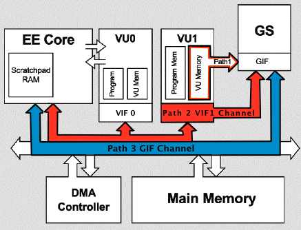
What is Path Three rendering? That’s the term usually used to describe a renderer that transforms vertexes and performs lighting calculations on the main EE MIPS CPU, using either plain C/C++ code or some inline assembly mix. This is what is sometimes called a “software renderer”, or “software vertex processing”. Once vertexes are transformed and lit on the EE CPU, the resulting screen-space data is sent to the GS (“Graphics Synthesizer”, the PS2 hardware rasterizer) to be textured and written to the framebuffer via the GIF DMA channel (the blue path in the image above).
This path is easy to use, the PS2DEV SDK libraries provide ready-to-use APIs to send data via the GIF channel and to control the GS rasterization, they even provide a couple usage samples, which helps a lot when getting started. That’s definitely were you start when doing PS2 homebrew development, and naturally was the approach I took when I started.
The downsides of this setup are that 1) you have to write code to perform vertex transformation (not something very usual nowadays) and 2) performance is not great.
Performance-wise, the main issue is with software vertex processing. The EE CPU is a MIPS R5900-based processor clocked at about 300MHz, which is snail-level slow if compared to modern processors. So you can imagine that in a game most of its processing power is already committed to game logic and simulation. Putting the vertex processing workload on the EE as well will not scale.
Another issue is with data uploads to the GS. The GIF DMA channel, which is the only direct path from the EE CPU to the GS, is normally already used as the path to transfer texture data from the main RAM to the video memory (VRam). The GS can only access textures that are already loaded into its tiny 4MB VRam cache, so the main EE CPU must be always shuffling textures from main RAM to VRam. This already places a lot of traffic on the GIF channel, so ideally we should reserve this channel just for texture data transfers.
That might all seem pretty bad, but overall you can get away with quite a bit using just path three rendering. My Dungeon Game demo uses path three only, but it is fairly complex, rendering-wise. It runs at around 30fps, with some eventual lower frame spikes, mostly cause by having a lot of particle systems in the view. I was able to get away with the software vertex processing in there, but I had to opt for no dynamic lighting, so the vertex processing stays as cheep as possible. This is not viable for Quake II, it uses dynamic lights. In my game I was also able to fine tune the content to meet these limitation, but on Quake, I’m porting and existing game and changing the art assets is not an option. So how does “path two” rendering improves on this?
Path Two rendering is the term generally used to describe vertex processing done in the Vector Unit 1 (VU1). This is very similar to what we today know as a Vertex Shader, so it is a kind of programmable hardware-accelerated vertex processing.
The VU1 can be programmed using an extended MIPS-based assembly language that supports SIMD instructions. It resembles a bit the old ARB assembly shaders from early programmable OpenGL hardware, while the rasterization remain fixed-function and done by the GS.
Thanks to its SIMD capabilities, the VU1 is perfect for vertex transformation and light calculations. It also has it’s private DMA channel, called the VIF (Vector Unit Interface), that links it with the EE CPU and the GS. So by doing vertex processing in the VU1 you not only move that workload to a separate processors but you also free the GIF channel for texture uploads.
Writing VU1 microprograms
So the Vector Unit 1 consists of a separate co-processor that runs in parallel with the main EE CPU where your C/C++ program lives. You can think of it as a video card on your modern PC, we can’t directly control it from our C code, instead we can only upload a microprogram to it’s local memory and send it some data for processing.
The VIF1 DMA channel is the only way your main program communicates with the VU1. You can send it data and executable code with async DMA transfers. Once it completes processing, you can instruct the VU1 to forward its results to the GS for further processing and finally screen display.
We start off with a VCL assembly program. The following is an example of a very simplistic VU1 microprogram that processes a single triangle. You might recognize are few instructions from the MIPS instruction set:
;;
;; test_triangle.vcl
;;
;; A VU1 microprogram to draw a single triangle.
;;

.syntax new
.name vu1Triangle
.vu
.init_vf_all
.init_vi_all

--enter
--endenter

    ; The model-view-projection matrix:
    lq mvpMatrixRow0, 0(vi00)
    lq mvpMatrixRow1, 1(vi00)
    lq mvpMatrixRow2, 2(vi00)
    lq mvpMatrixRow3, 3(vi00)

    ; A scale vector that we will use to
    ; scale the verts after projecting them.
    lq fScales, 4(vi00)

    iaddiu vertexData, vi00, 7
    iaddiu destAdress, vi00, 20
    iaddiu kickAdress, vi00, 20

    lq  gifTag, 5(vi00)
    sqi gifTag, (destAdress++)

    lq  color, 6(vi00)
    sqi color, (destAdress++)

    iaddiu vertexCounter, vi00, 3

    ;;
    ;; Loop for each of the 3 vertexes in the triangle:
    ;;
    vertexLoop:
        lqi vertex, (vertexData++)

        ; Transform each vertex by the MVP:
        mul  acc,    mvpMatrixRow0, vertex[x]
        madd acc,    mvpMatrixRow1, vertex[y]
        madd acc,    mvpMatrixRow2, vertex[z]
        madd vertex, mvpMatrixRow3, vertex[w]

        ; Divide by the W (perspective divide):
        div q, vf00[w], vertex[w]
        mul.xyz vertex, vertex, q

        ; Scale to GS screen-space and to fixed-point:
        mula.xyz  acc,    fScales, vf00[w] ; Move fScales into the accumulator (acc = fScales * 1.0)
        madd.xyz  vertex, vertex,  fScales ; Multiply and add the scales (Vert = Vert * fScales + fScales)
        ftoi4.xyz vertex, vertex           ; Convert the vertex to 12:4 fixed point for the GS

        ; Store the transformed vertex:
        sqi vertex, (destAdress++)

        ; Decrement the loop counter and repeat
        ; if not done with the triangle yet:
        iaddi vertexCounter, vertexCounter, -1
        ibne  vertexCounter, vi00, vertexLoop
    ; END vertexLoop

    ; Dispatch the triangle to the GS rasterizer.
    xgkick kickAdress

--exit
--endexit
This “high-level assembly” is not valid VU1 asm code per-say. If you pass it
to dvp-as is won’t assemble as-is. Running Open VCL on it yields the following “raw”
VU1 assembly microprogram:
.global vu1Triangle_CodeStart
.global vu1Triangle_CodeEnd

vu1Triangle_CodeStart:
                    .p2align 8
                    .vu
                    nop                             lq VF01, 0(VI00)
                    nop                             lq VF02, 1(VI00)
                    nop                             lq VF03, 2(VI00)
                    nop                             lq VF04, 3(VI00)
                    nop                             lq VF05, 4(VI00)
                    nop                             iaddiu VI01, VI00, 7
                    nop                             iaddiu VI02, VI00, 20
                    nop                             iaddiu VI03, VI00, 20
                    nop                             lq VF06, 5(VI00)
                    nop                             sqi VF06, (VI02++)
                    nop                             lq VF06, 6(VI00)
                    nop                             sqi VF06, (VI02++)
                    nop                             iaddiu VI04, VI00, 3
vertexLoop:
                    nop                             lqi VF06, (VI01++)
                    mulax ACC, VF01, VF06x          nop
                    madday ACC, VF02, VF06y         nop
                    maddaz ACC, VF03, VF06z         nop
                    maddw VF07, VF04, VF06w         nop
                    nop                             div q, VF00w, VF07w
                    nop                             waitq
                    mulq.xyz VF07, VF07, q          nop
                    mulaw.xyz ACC, VF05, VF00w      nop
                    madd.xyz VF07, VF07, VF05       nop
                    ftoi4.xyz VF07, VF07            nop
                    nop                             sqi VF07, (VI02++)
                    nop                             iaddi VI04, VI04, -1
                    nop                             nop
                    nop                             ibne VI04, VI00, vertexLoop
                    nop                             nop
                    nop                             xgkick VI03
                    nop[E]                          nop
                    nop                             nop
vu1Triangle_CodeEnd:
That can now be assembled with dvp-as from the free SDK. It will produce
a binary object file (.o) that you can embed into your ELF executable as raw data.
The assembler will always place the VU code inside a .vudata section†
which you can reference in C/C++ code as:
extern void vu1Triangle_CodeStart __attribute__((section(".vudata")));
extern void vu1Triangle_CodeEnd   __attribute__((section(".vudata")));
Notice the GCC-specific annotation to indicate the data is in the .vudata section.
Now that we have VU code compiled and embedded into our executable we still need to send it over to the VU1 for execution. This is done via the VIF DMA channel. We can transfer the program to VU1 code space upfront, then run it when it comes the time to render. The memory space for code is tiny, so we can only fit one or two programs in there at most. Only one can be run at a time. So you want to render as much stuff as possible with one program before uploading a new one.
Vertex data is sent to the VU1 in the same manner, through the VIF channel. If you’re curious about the details, be sure to check the current implementation I’m using on Quake II. It’s not very readable and uses a lot of macros and magic constants. I based most of it from existing Open Source samples and libraries that are not very documented either. Unfortunately there’s not a lot of official documentation on the PS2 hardware out there, so it is mostly just trial and error.
And why go through the trouble of embedding the VU microprogram into the executable, you might ask? Mostly because the generated binary is tiny (usually under a KB), so there’s little reason to place that into a separate file that you’d have to load on-the-fly. And also because you probably won’t be using a lot of these microprogram anyways. Having them readily available in the C code as pointers-to-static-data facilitates things from the programmer’s perspective.
† Trivia: If you extract the executable from a PS2 game disk and
run it through a tool like readelf it will probably have a .vudata
section. The original assembler provided by Sony also placed VU microcode inside a section
with that name, so the free SDK correctly emulates that behavior. This also makes it very
easy to dump VU microcode from existing games, but unfortunately I don’t know of any VU
disassembler that you could use to reverse-engineer and study VU programs from other PS2 games.
")
After you set everything up and send the vertex data to the VU1, the actual rendering
can take place. The main program running on the EE CPU just sends a packet of vertex
data in the VIF1 channel. When the VU1 is done processing the data it fires a xgkick
instruction that will send the results to the GS automatically through “path one”.
So on your renderer-side, instead of doing all the vertex processing and GIF data transfers,
all you have to do now is set up a data packet and send it to the VU1. Then wait for completion
and swap the display framebuffers. Above is my first VU1 accelerated triangle running inside the
Quake II engine.
What about the VU0?
As you might have figured out, there’s another Vector Unit processor in the system, the VU0. The first Vector Unit is linked directly to the EE processor an can be accessed via inline assembly from the C/C++ code. This mode of operation is called “macro mode”. Macro mode offers a more limited instruction set but can be used to accelerate parts of a software rendering pipeline on the EE. Actually, that’s exactly what I did on my Dungeon Game. I used VU0 inline assembly to accelerate some matrix and vector maths and speed up things like matrix*vector multiplication and projection. The VU0 can also be run in “micro mode”, which is the same way as the VU1 operates, running a local microprogram in it. This is the most performant way of using the VU0 and I’m sure the high-end games used it as such for things like physics calculations and animation blending. For the PS2 Quake port so far I think I’ll probably be able to get away with VU1 vertex processing and some VU0 inline assembly, so I probably won’t be exploring the VU0 high performance paths as of now.